General
The dual power automatic switch is a newly developed miniature household power switch, which is mainly used to test whether the main power supply or standby power supply is normal. When the normal power supply is abnormal, the standby power supply starts to work immediately, which ensures the continuity, reliability and safety of power supply. This product is specially designed for household rail installation and is specially used for PZ30 distribution box.
The dual power automatic switch is suitable for emergency power supply systems with 50 or 60Hz and rated 400V AC. ATS has the characteristics of solid structure, reliable conversion, convenient installation and maintenance and long service life. It is widely used in various occasions where power failure cannot be sustained, and can be operated by electricity or manually. ATS is composed of TSE and controller. According to GB/T14048.11, Part 6-1: multifunctional equipment and switchgear is formulated. It can be seen that ATS is the most qualified low-voltage switchgear and control device.
Installation and wiring
5.1 Ensure that professionals read this manual before installation and wiring.
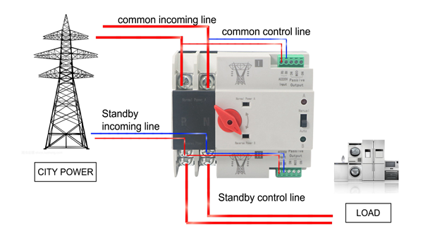
5.2 Please check the integrity of ATS before installation, then open and close ATS with the operating handle, check the flexibility of transmission device and detect the load generation and disconnection conditions of common and standby power supplies at each stage.
5.3 See the figure for the correct installation steps. The trademark is in front of the product. If the installation cannot be carried out according to the correct procedures due to wiring and other reasons, please contact us. The safe distances S1, S2 should not be lower than the labels in Fig. 8. (See figure below for details)
5.4 Detection control voltage: 50Hz, AC220V. The coil in the control circuit cannot be too long. The cross- sectional area of copper wire should not be greater than 2.0mm2.
5.5 According to the installation requirements of power distribution system, please provide appropriate circuit breakers to ensure the safety of staff and equipment.

Pole numbers | 2p | 3p | 4p |
length | 107.5 | 125 | 142.5 |
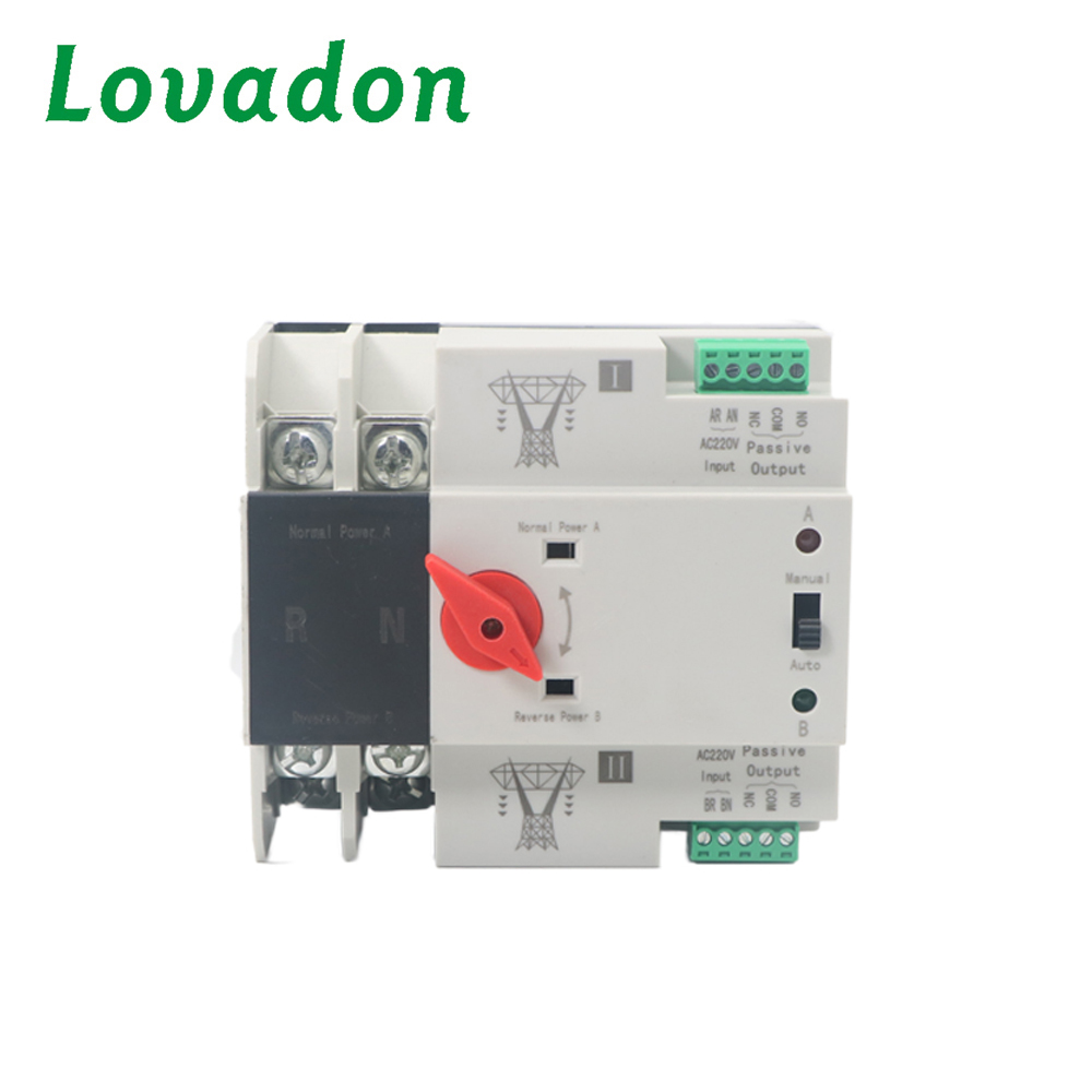
①Control power ⑤ Altemative powermain circuit terminal
②Selection switch(Auto/manual) ⑥ Load side main circuit terminal
③Manual knob ⑦Power A indicator
④Normal power main circuit terminal ⑧ Power B indicator
Technical Parameters
| Specification | 100A |
| Rated current Ie(A) | 16,20,25 32 40 50 63 | 100 |
| Insulation voltage Ui | AC 690V,50HZ |
| Rated voltage Ue | AC400V,50HZ |
| Classification | PC class:can be manufactured and withstood without short circuit current |
| Utilization category | AC-33iB |
| Pole No. | 2P | 3P | 4P |
| Weight(kg) | 0.62 | 0.72 | 0.81 |
| Electrical | Life: 2000 times;Manual operation:5000times |
| Rated short circuit current Iq | 50kA |
| Short circuit protection device (fuse) | RT16-00-63A |
| Rated impluse withstand voltage | 8kV |
| Control circuit | Rated control voltage Us:AC220V/50HZ Normal working conditions:85-110%Us |
| Auxiliary circuit | 2 relays ,each of contact converter contact capacity:AC220v/50hz Ie=5y |
| Conversion time of contactor | <50ms |
| Operation conversion time | <50ms |
| return conversion time | <50ms |
| power off time | <50ms |
| switching time | 8ms |
| Temperature range | -5℃-40℃ average temperature not more than 35℃ in 24hours |

 Yueqing Lovadon Electric Co., Ltd.